Before you wire up your first ESP32 circuit, you need to understand a handful of fundamental concepts. This is not a full electronics course -- it is the minimum you need to safely connect components and understand what is happening in your circuits.
🔗Voltage, current, and resistance
These three quantities are the foundation of every circuit. Think of electricity flowing through a wire like water flowing through a pipe:
- Voltage (V) is the pressure that pushes electricity through a circuit. It is measured in volts (V). A USB port provides 5 V; the ESP32 operates at 3.3 V logic.
- Current (I) is the amount of electricity flowing. It is measured in amperes (A), usually milliamps (mA) for our purposes. A typical LED draws about 20 mA.
- Resistance (R) is how much a component opposes the flow of current. It is measured in ohms ($\Omega$). A resistor limits current to protect components.
🔗Ohm's law
These three quantities are related by one of the most important equations in electronics:
$$V = I \cdot R$$
This can be rearranged depending on what you need to find:
$$I = \frac{V}{R} \qquad R = \frac{V}{I}$$
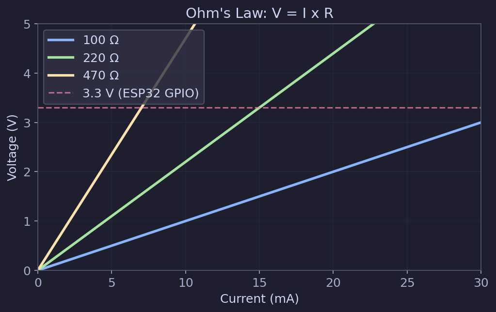
The chart below shows this relationship in action -- for a given resistor value, current and voltage are proportional. Higher resistance means less current flows at the same voltage:
Practical example: You want to power an LED from a 3.3 V GPIO pin. The LED has a forward voltage of about 2 V and should draw about 10 mA ($0.01 \, \text{A}$). What resistor do you need?
The resistor must drop the remaining voltage:
$$R = \frac{V_{pin} - V_{LED}}{I} = \frac{3.3 - 2.0}{0.01} = 130 \, \Omega$$
The nearest common resistor value is 150 $\Omega$ or 220 $\Omega$. Either works fine -- using a slightly higher resistance just means the LED will be a bit dimmer. A 220 $\Omega$ resistor is a safe, common choice for LEDs driven from 3.3 V.
🔗Power
Power is how much energy a component uses per second. It is measured in watts (W):
$$P = V \cdot I$$
You can also derive:
$$P = I^2 \cdot R = \frac{V^2}{R}$$
Why this matters: Every component has a power rating. A standard 1/4 W resistor can safely dissipate 0.25 W. If your circuit would push more power through it, the resistor will overheat. For most ESP32 beginner projects, power levels are very low and this is not a concern -- but it is good to understand the concept.
Example: That 220 $\Omega$ resistor with 10 mA flowing through it dissipates:
$$P = I^2 \cdot R = (0.01)^2 \times 220 = 0.022 \, \text{W}$$
That is well within the 0.25 W rating of a standard resistor.
🔗Voltage: 3.3 V vs 5 V logic
This is critical for ESP32 work.
The ESP32 runs on 3.3 V logic. This means:
- A "HIGH" signal from a GPIO pin is 3.3 V
- A "LOW" signal is 0 V (ground)
- The GPIO pins can tolerate a maximum of 3.3 V input
Many Arduino boards and some sensors operate at 5 V logic. If you connect a 5 V output directly to an ESP32 GPIO pin, you can damage the chip.
Warning: Never apply more than 3.3 V to an ESP32 GPIO pin. If you need to interface with 5 V devices, use a logic level converter or a voltage divider.
The ESP32 development board itself is usually powered through USB (5 V), but the onboard voltage regulator steps this down to 3.3 V for the chip. The 3V3 pin on the board provides regulated 3.3 V that you can use to power sensors and other 3.3 V components.
🔗Ground: the reference point
Ground (GND) is the common reference point in a circuit. All voltages are measured relative to ground. When we say a GPIO pin outputs 3.3 V, we mean 3.3 V above ground.
Every component in your circuit needs a path back to ground. If you are connecting a sensor to the ESP32, the sensor's GND pin must be connected to the ESP32's GND pin. This is one of the most common mistakes beginners make -- forgetting to connect grounds together.
Tip: When connecting multiple components to your ESP32, always make sure they share a common ground. Without a shared ground, signals between components will not work correctly.
🔗Series vs parallel circuits
Components can be connected in two basic arrangements:
🔗Series
Components connected end-to-end, forming a single path for current. The same current flows through every component.
- Resistors in series add up: $R_{total} = R_1 + R_2 + R_3$
- Voltage divides across each component proportionally
- If one component fails (opens), the entire path breaks
🔗Parallel
Components connected side-by-side, each with its own path from power to ground. The voltage across each component is the same.
- Resistors in parallel follow: $\frac{1}{R_{total}} = \frac{1}{R_1} + \frac{1}{R_2} + \frac{1}{R_3}$
- Current divides among the branches
- If one component fails, the others keep working
🔗The voltage divider
A voltage divider is two resistors in series, used to reduce a voltage. This is something you will encounter frequently in ESP32 projects, for example when reading a sensor that outputs a voltage higher than 3.3 V.
graph LR
    Vin["V_in"] --> R1["R1"]
    R1 --> Vout["V_out"]
    Vout --> R2["R2"]
    R2 --> GND["GND"]
The output voltage is:
$$V_{out} = V_{in} \cdot \frac{R_2}{R_1 + R_2}$$
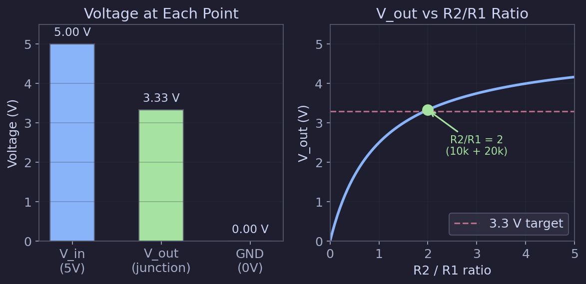
Example: To step 5 V down to approximately 3.3 V, you could use $R_1 = 10 \, \text{k}\Omega$ and $R_2 = 20 \, \text{k}\Omega$:
$$V_{out} = 5 \cdot \frac{20{,}000}{10{,}000 + 20{,}000} = 5 \cdot \frac{2}{3} \approx 3.33 \, \text{V}$$
🔗Reading resistor values
Resistors are marked with colored bands that encode their value. For a 4-band resistor:
| Band | Meaning |
|---|---|
| 1st band | First digit |
| 2nd band | Second digit |
| 3rd band | Multiplier (number of zeros) |
| 4th band | Tolerance |
Common color codes:
| Color | Digit | Multiplier |
|---|---|---|
| Black | 0 | 1 |
| Brown | 1 | 10 |
| Red | 2 | 100 |
| Orange | 3 | 1,000 |
| Yellow | 4 | 10,000 |
| Green | 5 | 100,000 |
| Blue | 6 | 1,000,000 |
| Violet | 7 | -- |
| Grey | 8 | -- |
| White | 9 | -- |
| Gold | -- | 0.1 (tolerance: 5%) |
| Silver | -- | 0.01 (tolerance: 10%) |
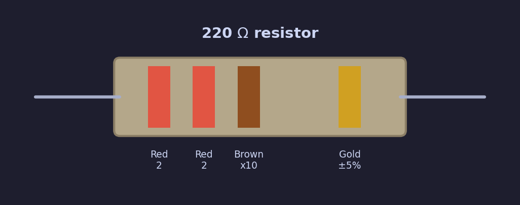
Example: A resistor with bands Red, Red, Brown, Gold = 2, 2, x10 = 220 $\Omega$, 5% tolerance.
Tip: If you find color codes hard to read (many people do -- especially with small resistors or poor lighting), just use a multimeter set to resistance mode ($\Omega$). Touch the probes to each end of the resistor and read the value directly. A multimeter is one of the most useful tools you can own.
🔗Practical summary
Here is what you need to remember for ESP32 projects:
| Concept | Key takeaway |
|---|---|
| Voltage | The ESP32 uses 3.3 V logic. Never exceed this on GPIO pins. |
| Current | Most ESP32 GPIO pins can source up to about 12 mA safely. Use resistors to limit current. |
| Ohm's law | $V = I \cdot R$ -- use it to calculate resistor values for LEDs and other components. |
| Ground | Always connect grounds together. Every device needs a common ground reference. |
| Power | $P = V \cdot I$ -- check that components stay within their power ratings. |
| 3.3 V vs 5 V | Use a level shifter or voltage divider when interfacing with 5 V devices. |
These fundamentals will come up again and again as you build circuits. You do not need to memorize everything now -- you can always come back to this page as a reference.
🔗Next steps
Now that you understand the basic electrical concepts, the next article covers the specific components you will need to buy for your first ESP32 projects.