So far, you have used digital output to turn an LED on and off. But the world is not just on and off -- temperature changes gradually, light dims smoothly, and a potentiometer turns continuously. This article explains the difference between digital and analog signals on the ESP32, and how to work with both.
🔗Digital signals: on or off
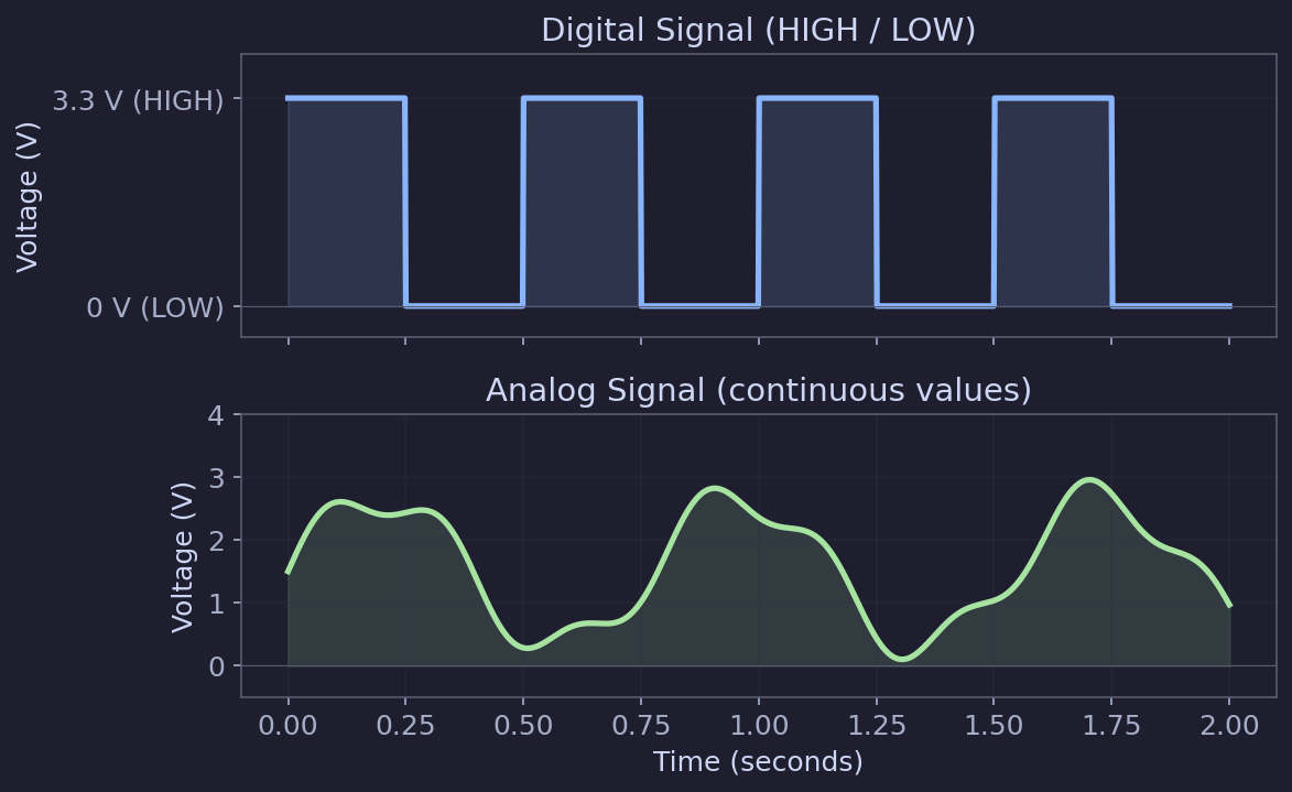
A digital signal has only two states:
| State | Voltage | Arduino constant |
|---|---|---|
| HIGH | 3.3 V | HIGH or 1 |
| LOW | 0 V | LOW or 0 |
There is nothing in between. When you write digitalWrite(pin, HIGH), the pin outputs 3.3 V. When you write digitalWrite(pin, LOW), it outputs 0 V.
Digital signals are perfect for things that are naturally binary: an LED that is on or off, a relay that is open or closed, a button that is pressed or not.
🔗Digital output: digitalWrite()
You already used this in the blink sketch:
pinMode(LED_PIN, OUTPUT);
digitalWrite(LED_PIN, HIGH);  // 3.3 V out
digitalWrite(LED_PIN, LOW); // 0 V out🔗Digital input: digitalRead()
To read a button or switch, configure the pin as an input and use digitalRead():
int state = digitalRead(BUTTON_PIN); // Returns HIGH or LOW🔗Practical example: read a push button
Let's wire up a button and read its state.
🔗Wiring
| ESP32 pin | Connects to |
|---|---|
| GPIO 14 | One side of push button |
| GND | Other side of push button |
That is it -- just two wires. We will use the ESP32's internal pull-up resistor instead of an external one.
🔗How the pull-up works
Without a pull-up resistor, an unconnected input pin "floats" -- it reads random HIGH and LOW values because it is not connected to anything definite. A pull-up resistor ties the pin to 3.3 V so it reads HIGH by default. When you press the button, it connects the pin to GND, pulling it LOW.
The ESP32 has built-in pull-up resistors that you can activate in software with INPUT_PULLUP, so you do not need an external resistor.
graph LR
    V["3.3V (internal)"] ---|Pull-up R| P["GPIO 14"]
    P --- B["Button"]
B --- G["GND"]- Button not pressed: GPIO 14 is pulled HIGH (3.3 V) by the internal resistor
- Button pressed: GPIO 14 is connected directly to GND, reading LOW (0 V)
Note: Because of the pull-up, the logic is inverted from what you might expect. LOW means pressed, HIGH means not pressed.
🔗Code
#define BUTTON_PIN 14
#define LED_PIN 2

void setup() {
  pinMode(BUTTON_PIN, INPUT_PULLUP);  // Enable internal pull-up resistor
  pinMode(LED_PIN, OUTPUT);
  Serial.begin(115200);
  delay(1000);
}

void loop() {
  int buttonState = digitalRead(BUTTON_PIN);

  if (buttonState == LOW) {       // LOW = pressed (pull-up logic)
    digitalWrite(LED_PIN, HIGH);  // Turn LED on
    Serial.println("Button pressed");
  } else {
    digitalWrite(LED_PIN, LOW);   // Turn LED off
  }

  delay(50);  // Small delay for debouncing
}
Upload this and press the button -- the built-in LED should light up while the button is held down.
Tip: The 50 ms delay at the end of
loop()provides simple debouncing. Mechanical buttons often "bounce" -- rapidly toggling between connected and disconnected for a few milliseconds when pressed. The delay prevents the code from reading these bounces as multiple presses. For more reliable debouncing in real projects, use a library or track timing withmillis().
🔗Analog signals: continuous values
Unlike digital signals, analog signals can be any voltage within a range. A temperature sensor might output 0.8 V at room temperature and 1.5 V in the sun. A potentiometer smoothly varies from 0 V to 3.3 V as you turn the knob.
🔗The ADC: Analog-to-Digital Converter
To read analog signals, the ESP32 uses an ADC (Analog-to-Digital Converter). The ADC measures the voltage on a pin and converts it to a number.
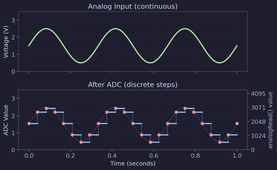
The ESP32's ADC is 12-bit, which means it maps the input voltage to a value between 0 and 4095:
| Voltage at pin | analogRead() value |
|---|---|
| 0 V | 0 |
| 1.65 V | ~2048 |
| 3.3 V | 4095 |
The resolution is:
$$\frac{3.3 \, \text{V}}{4095} \approx 0.000806 \, \text{V per step} \approx 0.8 \, \text{mV}$$
🔗Which pins have ADC?
The ESP32-WROOM-32 has two ADC units:
| ADC unit | GPIO pins | Notes |
|---|---|---|
| ADC1 | 32, 33, 34, 35, 36, 39 | Always available |
| ADC2 | 0, 2, 4, 12, 13, 14, 15, 25, 26, 27 | Cannot be used while WiFi is active |
Warning: ADC2 shares hardware with the WiFi radio. If your project uses WiFi (which most IoT projects do), you can only use ADC1 pins for analog readings. This catches many beginners off guard -- if
analogRead()returns garbage values, check whether you are using an ADC2 pin while WiFi is connected.
Also note: GPIOs 34, 35, 36, and 39 are input-only on the classic ESP32. They cannot be used as outputs. This makes them great for analog reads, since you are using them as inputs anyway.
The exact ADC pins available may vary by board. Not all boards expose all pins -- always check your board's pinout diagram.
🔗Practical example: read a potentiometer
A potentiometer (or "pot") is a variable resistor with a knob. It has three pins and works as an adjustable voltage divider.
🔗Wiring
| Potentiometer pin | Connects to |
|---|---|
| Left pin | 3.3V |
| Middle pin (wiper) | GPIO 34 |
| Right pin | GND |
Tip: We use GPIO 34 because it is on ADC1 (works even with WiFi) and is input-only (which is fine since we are reading a value).
🔗Code
#define POT_PIN 34

void setup() {
  Serial.begin(115200);
  delay(1000);
  Serial.println("Potentiometer reader");
}

void loop() {
  int rawValue = analogRead(POT_PIN);

  // Convert to voltage
  float voltage = rawValue * (3.3 / 4095.0);

  Serial.print("Raw: ");
  Serial.print(rawValue);
  Serial.print("  Voltage: ");
  Serial.print(voltage, 2);  // 2 decimal places
  Serial.println(" V");

  delay(200);
}
Open the Serial Monitor and turn the potentiometer knob. You should see values smoothly changing from 0 to 4095 (and 0 V to 3.3 V).
🔗ADC limitations
The ESP32's ADC is good enough for most hobbyist projects, but it has some quirks:
- Non-linear at extremes. Readings near 0 V and 3.3 V can be inaccurate. The ADC is most reliable between about 0.15 V and 2.45 V.
- Noise. Single readings can fluctuate. For more stable results, take multiple samples and average them:
int readADC(int pin, int samples) {
  long total = 0;
  for (int i = 0; i < samples; i++) {
    total += analogRead(pin);
    delay(1);
  }
  return total / samples;
}- ADC2 and WiFi conflict. As mentioned above, avoid ADC2 pins if you are using WiFi.
For applications that need high accuracy, consider an external ADC module like the ADS1115 (16-bit, connected via I2C). But for reading potentiometers, light sensors, and soil moisture sensors, the built-in ADC works well.
🔗Analog output: PWM
Here is a common point of confusion: the ESP32 does not have true analog output on its GPIO pins. If you try analogWrite() as you might on an Arduino Uno, it will not work -- the function does not exist in the ESP32 Arduino framework.
Instead, the ESP32 uses PWM (Pulse Width Modulation) to simulate analog output. PWM rapidly switches a pin between HIGH and LOW. By varying how much time the pin spends HIGH versus LOW, you can control the average voltage that a component sees.
The percentage of time the signal is HIGH is called the duty cycle:
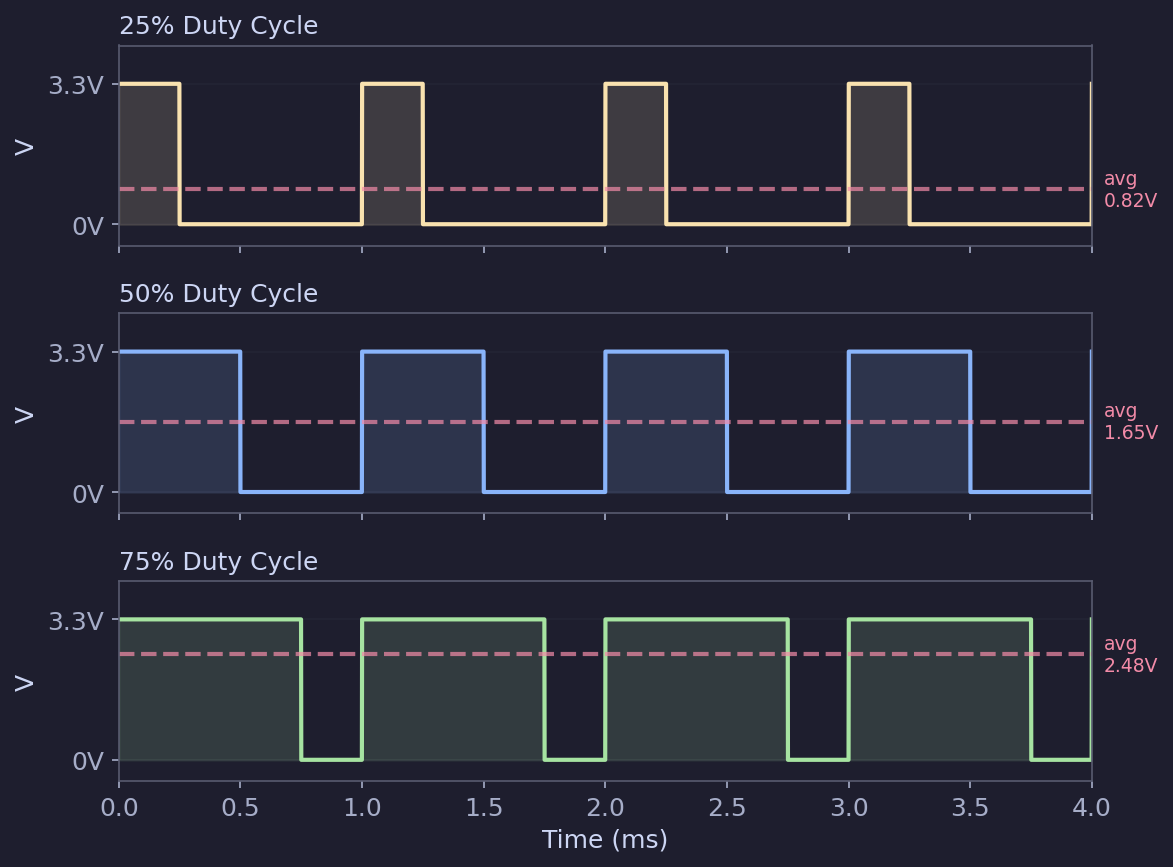
| Duty cycle | Average voltage | Effect on LED |
|---|---|---|
| 0% | 0 V | Off |
| 25% | ~0.83 V | Dim |
| 50% | ~1.65 V | Medium |
| 75% | ~2.48 V | Bright |
| 100% | 3.3 V | Full brightness |
🔗ESP32 PWM functions
The ESP32 Arduino framework uses ledcAttach() and ledcWrite() for PWM. Despite the "ledc" name (it stands for LED Control), these functions work for any PWM application -- LEDs, motors, buzzers, and more.
ledcAttach(pin, frequency, resolution);  // Configure PWM on a pin
ledcWrite(pin, dutyCycle); // Set the duty cycle- pin -- The GPIO pin to use
- frequency -- PWM frequency in Hz (5000 is common for LEDs)
- resolution -- Bit depth of the duty cycle (8 bits = 0-255, 10 bits = 0-1023)
🔗Practical example: dim an LED with PWM
🔗Wiring
Same as the external LED from the previous article:
| ESP32 pin | Connects to |
|---|---|
| GPIO 13 | 220 $\Omega$ resistor, then to LED anode (long leg) |
| GND | LED cathode (short leg) |
🔗Code: smooth fade
#define LED_PIN 13
#define PWM_FREQ 5000      // 5 kHz - too fast for the eye to see flicker
#define PWM_RESOLUTION 8   // 8-bit: duty cycle values 0-255

void setup() {
  ledcAttach(LED_PIN, PWM_FREQ, PWM_RESOLUTION);
  Serial.begin(115200);
  delay(1000);
  Serial.println("PWM LED fade");
}

void loop() {
  // Fade in
  for (int duty = 0; duty <= 255; duty++) {
    ledcWrite(LED_PIN, duty);
    delay(5);
  }

  // Fade out
  for (int duty = 255; duty >= 0; duty--) {
    ledcWrite(LED_PIN, duty);
    delay(5);
  }
}
Upload this and watch the LED smoothly fade in and out. Each full fade cycle takes about $255 \times 5 \, \text{ms} \times 2 \approx 2.5 \, \text{s}$.
🔗Code: potentiometer-controlled brightness
Combine analog input with PWM output -- use the potentiometer to control LED brightness:
#define POT_PIN 34
#define LED_PIN 13
#define PWM_FREQ 5000
#define PWM_RESOLUTION 8   // 0-255

void setup() {
  ledcAttach(LED_PIN, PWM_FREQ, PWM_RESOLUTION);
  Serial.begin(115200);
  delay(1000);
}

void loop() {
  int potValue = analogRead(POT_PIN);       // 0-4095
  int brightness = potValue / 16;           // Scale to 0-255

  ledcWrite(LED_PIN, brightness);

  Serial.print("Pot: ");
  Serial.print(potValue);
  Serial.print("  Brightness: ");
  Serial.println(brightness);

  delay(50);
}
Turn the potentiometer and the LED brightness follows. This is a great demonstration of reading an analog input and using it to control a PWM output.
Note about the DAC: The ESP32 does have two true analog output pins (DAC1 on GPIO 25, DAC2 on GPIO 26) that output a real voltage rather than a PWM signal. They are 8-bit (0-255 maps to 0-3.3 V). You can use them with
dacWrite(pin, value). However, PWM vialedcWrite()is more commonly used because it works on any GPIO pin and is more versatile.
🔗GPIO pin summary
Here is a quick reference for which pins to use for what on the ESP32-WROOM-32:
| Function | Recommended pins | Notes |
|---|---|---|
| Digital output | Most GPIOs (e.g., 2, 4, 5, 13, 16-33) | Avoid strapping pins (0, 2, 5, 12, 15) during boot |
| Digital input | Any GPIO | Use INPUT_PULLUP for buttons |
| Analog input (ADC1) | 32, 33, 34, 35, 36, 39 | Use these for analog reads, especially with WiFi |
| Analog input (ADC2) | 0, 2, 4, 12-15, 25-27 | Not available when WiFi is active |
| PWM output | Any output-capable GPIO | Use ledcAttach() and ledcWrite() |
| Input-only pins | 34, 35, 36, 39 | Cannot be used as outputs |
| DAC output | 25, 26 | True 8-bit analog output |
Reminder: Not all boards expose all pins, and pin labels can differ between board manufacturers. Always refer to the pinout diagram for your specific board.
🔗What you learned
In this article you:
- Understood the difference between digital (HIGH/LOW) and analog (continuous) signals
- Read a push button using
digitalRead()and internal pull-up resistors - Read a potentiometer using
analogRead()and the ESP32's 12-bit ADC - Learned about ADC limitations: non-linearity, noise, and the ADC2/WiFi conflict
- Used PWM with
ledcAttach()andledcWrite()to dim an LED (sinceanalogWrite()does not exist on ESP32) - Combined analog input and PWM output to create a potentiometer-controlled LED
🔗Next steps
You now have the fundamental skills to control digital and analog I/O on the ESP32. From here, you are ready to explore real sensors and actuators. Check out the Sensors section to start reading temperature, light, distance, and more, or visit Projects for complete guided builds.